Monday, December 22, 2008

Putting it Together

The memory of the S7-200 is divided into three areas: program
space, data space, and configurable parameter space.

• Program space stores the ladder logic (LAD) or statement
list (STL) program instructions. This area of memory controls
the way data space and I/O points are used. LAD or STL
instructions are written using a programming device such as
a PC, then loaded into program memory of the PLC.

• Data space is used as a working area, and includes memory
locations for calculations, temporary storage of intermediate
results and constants. Data space includes memory
locations for devices such as timers, counters, high-speed
counters, and analog inputs and outputs. Data space can be
accessed under program control.


• Configurable parameter space, or memory, stores either the
default or modified configuration parameters.
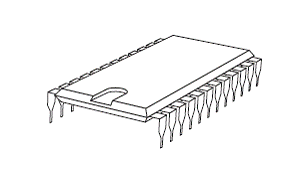
Firmware

Firmware is user or application specific software burned into
EPROM and delivered as part of the hardware. Firmware gives
the PLC its basic functionality.

Types Of Memory and its description

RAM
Random Access Memory (RAM) is memory where data can be
directly accessed at any address. Data can be written to and
read from RAM. RAM is used as a temporary storage area.
RAM is volatile, meaning that the data stored in RAM will be
lost if power is lost. A battery backup is required to avoid losing
data in the event of a power loss.

ROM
Read Only Memory (ROM) is a type of memory that data can
be read from but not written to. This type of memory is used
to protect data or programs from accidental erasure. ROM
memory is nonvolatile. This means a user program will not lose
data during a loss of electrical power. ROM is normally used to
store the programs that define the capabilities of the PLC.

EPROM
Erasable Programmable Read Only Memory (EPROM) provides
some level of security against unauthorized or unwanted
changes in a program. EPROMs are designed so that data
stored in them can be read, but not easily altered. Changing
EPROM data requires a special effort. UVEPROMs (ultraviolet
erasable programmable read only memory) can only be erased
with an ultraviolet light. EEPROM (electronically erasable
programmable read only memory), can only be erased
electronically.

Memory Size

Kilo, abbreviated K, normally refers to 1000 units. When talking
about computer or PLC memory, however, 1K means 1024. This
is because of the binary number system (210=1024). This can be
1024 bits, 1024 bytes, or 1024 words, depending on memory
type.

Hardware

Hardware is the actual equipment. The PLC, the programming
device, and the connecting cable are examples of hardware.


Software

Software is any information in a form that a computer or PLC
can use. Software includes the instructions or programs that
direct hardware.

PLC Scan

The PLC program is executed as part of a repetitive process
referred to as a scan. A PLC scan starts with the CPU reading
the status of inputs. The application program is executed using
the status of the inputs. Once the program is completed, the
CPU performs internal diagnostics and communication tasks.
The scan cycle ends by updating the outputs, then starts over.
The cycle time depends on the size of the program, the number
of I/Os, and the amount of communication required.


Function Block Diagrams

Function Block Diagrams (FBD) provide another view of a set of
instructions. Each function has a name to designate its specific
task. Functions are indicated by a rectangle. Inputs are shown
on the left-hand side of the rectangle and outputs are shown on
the right-hand side. The function block diagram shown below
performs the same function as shown by the ladder diagram
and statement list

Ladder Logic

Ladder logic (LAD) is one programming language used with
PLCs. Ladder logic uses components that resemble elements
used in a line diagram format to describe hard-wired control.
Refer to the STEP course Basics of Control Components for
more information on line diagrams.
STEP 2000


Image

Programming

A program consists of one or more instructions that accomplish
a task. Programming a PLC is simply constructing a set of
instructions. There are several ways to look at a program such
as ladder logic, statement lists, or function block diagrams.


Image